

The waste shaft
Garbage chute systems for towers and buildings in Saudi Arabia
One shaft, every floor, and no waste trolleys in the lift lobby.
A garbage chute is a sealed stainless shaft running the height of the building, with an intake door on each floor. A resident or a member of staff opens the nearest door, puts the bag in, and it arrives in the waste room in a few seconds. Nothing is carried through a corridor, and the handling happens in one place at the bottom where it can be managed properly.
Planning a chute? Read the guide: garbage chute requirements in Saudi Arabia.
It is also called a trash chute, a rubbish chute or a refuse chute, and the system as a whole a waste chute or central waste system. The names differ from drawing to drawing; the system is one.
The shaft
Stainless steel, and the details that decide it
- AISI 304 or 316 grade. 304 for a standard residential or commercial shaft, 316 where the waste stream or the coastal atmosphere is more aggressive. Both are selected rather than assumed.
- Sound-dampening paint on the shaft exterior. A bag falling thirty floors inside a steel tube is loud, and the shaft usually runs past bedrooms. It is the first thing removed from a cheaper offer — worth confirming it is in the package you are quoted.
- Offset tubes at the base absorb the impact of the falling bag before it reaches the discharge equipment, so the bag arrives rather than bursts.
- Clamp rings at every joint hold the sections and keep the interior continuous. A chute's performance over twenty years is decided at the joints.
Intake doors
One hand to open, and only one door at a time
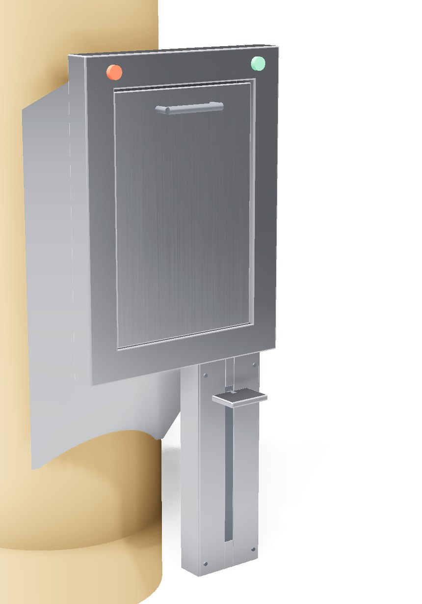
Stainless steel grade 304, bottom hinged, noiseless, self-sealing and self-closing, so the door opens with one hand and closes under control rather than slamming. A foot pedal version opens it hands-free.
Fire rated doors are available, and the rating is confirmed per project. Which rating is required comes from the project's fire strategy and the authority having jurisdiction, not from the chute supplier. We state the tested rating for the exact door and wall arrangement being supplied, with the manufacturer's test certificate, so the consultant can close the item — and we do not quote a rating a door has not been tested to.
Electromagnetic interlocking prevents two doors opening at the same time anywhere in the shaft. This is a safety function first — it stops a bag passing an open door on another floor — and an odour function second. Pilot lamps at each door show locked or unlocked, so a user waits rather than forces.
Electrical locking by floor or by schedule is available, which matters in a building where the chute should not be usable overnight, or on a floor under renovation.
The complaint you are preventing
Odour and noise control
A chute shaft connects every floor of the building to every other floor. Controlling what travels through it is the whole engineering problem.
- Extraction at the top of the shaft keeps it under negative pressure, so air moves up and out rather than into a corridor when a door is opened
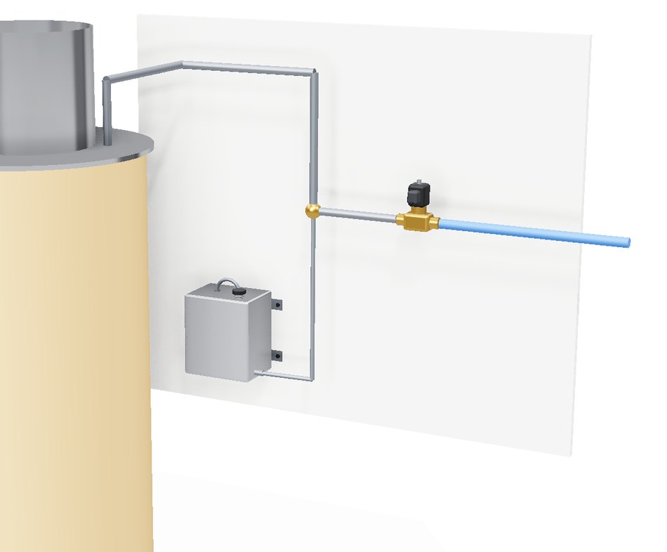
- A cleaning unit runs water and disinfection liquid down the shaft interior on a set cycle, mechanically or electrically operated
- The interlock limits how long any door is open
- Sound-dampening paint on the shaft exterior
All four run from one control panel, which operates the doors, the cleaning cycle and the exhaust fan together. One point of control and one point of fault-finding for the facility team.
At the bottom
Where the chute lands
The shaft is half the system. What sits at the bottom decides the operating cost.
| Arrangement | When it suits |
|---|---|
| A trolley | The simplest arrangement, for a building where collection is frequent |
| A compactor | Reduces the volume so the same bin holds considerably more, and the truck comes less often |
| A bi-sorter or tri-sorter | Diverts each stream into its own bin, so one shaft serves separated waste |
Debris chutes for construction and renovation
A different product and a different buyer — the contractor rather than the building owner. HDPE hopper tubes on galvanised supporting frames, with intake hoppers at intermediate floors, dropping debris from a working level into a skip at ground. They go up for the duration of the works and come down afterwards.
Useful on a refurbishment inside an occupied building, where the alternative is carrying material through finished areas.
Sizing
The diameter, and what decides it
A chute is specified by diameter, and the diameter is decided by what will be put into it rather than by the height of the building.
| Diameter | Typically suits |
|---|---|
| 500 mm | Apartment floors where the waste is bagged domestic waste and nothing else. |
| 600 mm | The common choice for residential towers and hotels. Takes a full kitchen bag without the user having to force it. |
| 700 mm | Commercial and mixed-use floors, where nobody controls what size the bag is. |
| 800 mm | Specialised cases. Rarely needed for waste, and worth questioning when it is proposed. |
Diameter is one of three numbers that have to agree: the barrel, the intake door opening, and the clear shaft the structural engineer leaves. Fixing one without the other two is the most common coordination error on this package.
- Route it straight. Every offset is a place where a bag slows down, and two bags that slow down in the same place are a blockage. Where an offset is unavoidable it has to be shallow and short.
- Cardboard is what actually blocks a chute. Not volume, and not weight. A flattened box opens out inside the barrel and catches. This is a signage and housekeeping matter as much as an engineering one, and it is worth settling before handover rather than after the first complaint.
- The door height is an ergonomic decision. Too high and the user lifts a heavy bag to shoulder level; too low and they bend with it. A bottom-hinged door at roughly waist height is what makes the system get used instead of worked around.
- Service access. The cleaning unit, the extraction fan and the top of the shaft all need to be reachable by a technician, from a position that is safe to stand in. This is designed in, or it is a permanent maintenance problem.
The system
What a complete garbage chute system is made of
A trash chute is not one product. It is a stainless shaft, a door on every floor, a cleaning system, fire protection, a control panel, and whatever receives the waste at the bottom — and all of it is specified together.
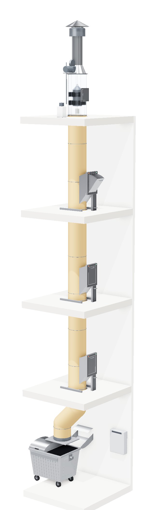
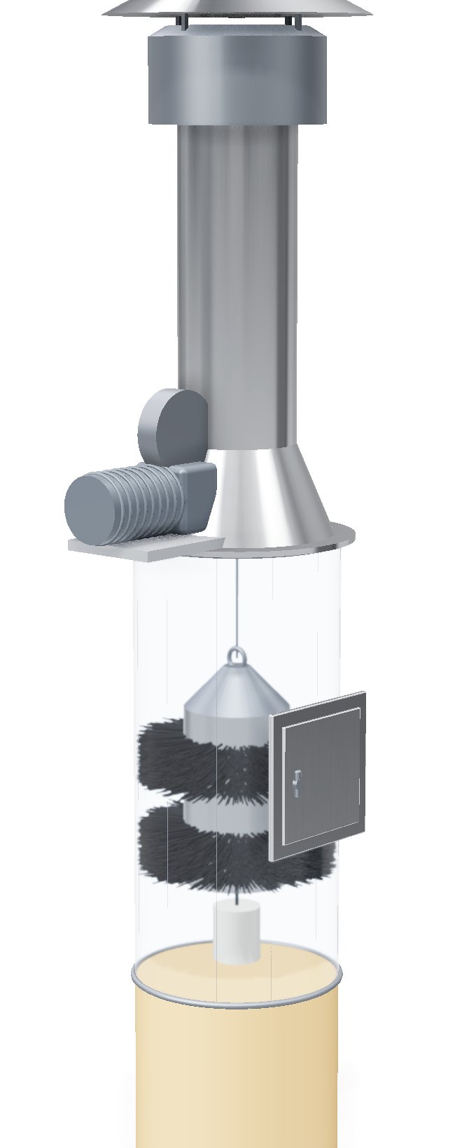
- Exhaust fan and chute vent. At roof level, on a Ø340 mm vent neck from the chute head plate. It holds the shaft under negative pressure so odour leaves the building instead of entering the lobby.
- Chute head plate. Stainless steel AISI 304, 1.5 mm, with the vent neck at the centre and pre-drilled openings for the flushing spray head and air vent. The plate lifts off for maintenance.
- Brushing device. A cylindrical holder with detachable stiff nylon brushes, parked in the top section behind an access door. A geared motor lowers it on a steel rope down the full height of the shaft and returns it.
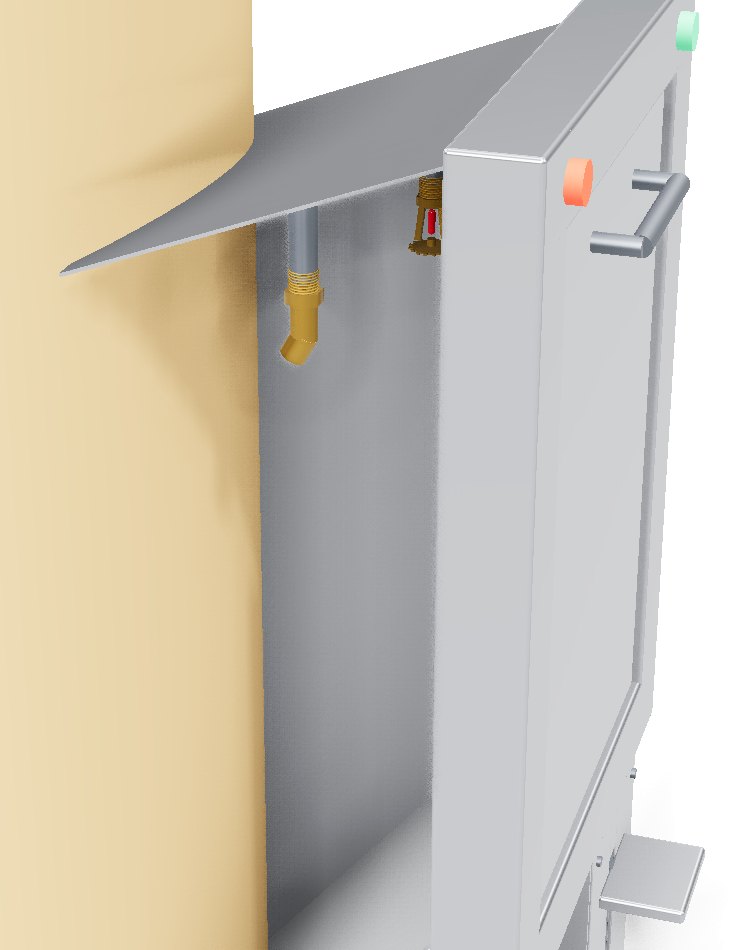
- Jet spray at every intake. A brass nozzle inside each intake throat, plus one on the head plate, spraying water mixed with disinfectant into the chute during the cleaning cycle.
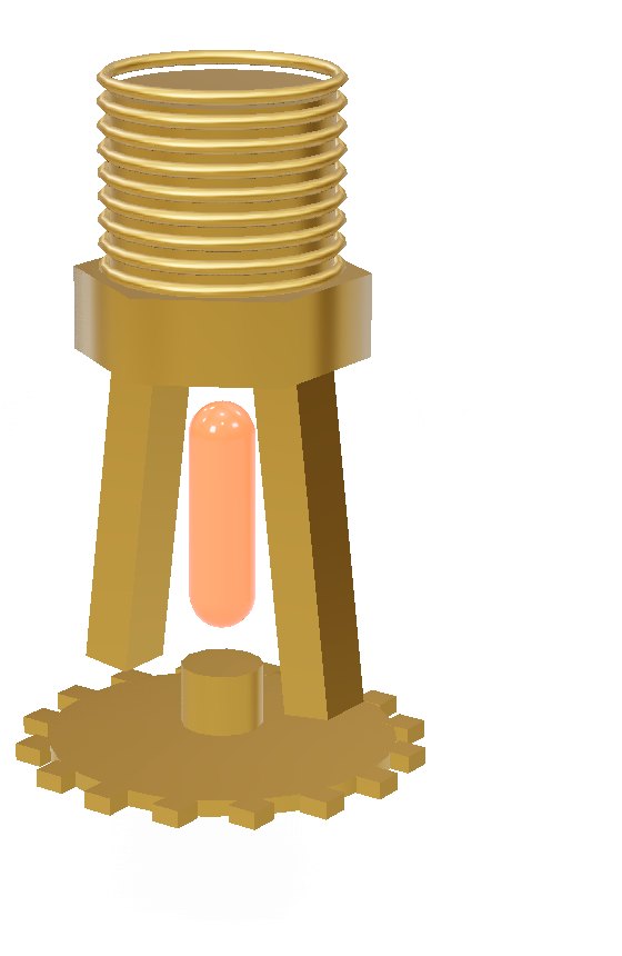
- Glass bulb sprinkler at every intake. Pendent type, ½", activating at 68 °C, inside the throat on the right side.
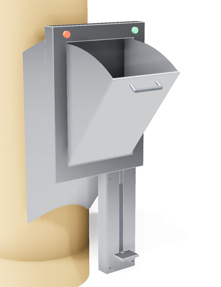
- Fire rated intake door. Bottom hinged stainless hopper door, interlocked so only one door on the shaft can open at a time, with pilot lamps and optional foot pedal.
- Master control panel. In the ground floor waste room. It runs the door interlock, the cleaning cycle and the exhaust fan.
- At the bottom. Two 45° bends above the waste room take the shaft over the container, the compactor or the sorter.
Specification
The garbage chute system, in numbers
This is the specification we submit. The full material submittal, with the manufacturer's drawings, is downloadable at the bottom of this page.
| Chute tube | Ø600 mm, stainless steel grade 304, 1.5 mm, rolled section, butt jointed and MIG welded, with a Ø8 mm ring at each end. Supplied to the actual building height. |
| Sound dampening | Factory-applied dampening compound over the full outer surface of the tube. Any metal chute is noisy; the coating is what stops a bag at the eleventh floor being heard on the third. Damage in transport or installation is made good on site. |
| Chute head plate | Stainless steel AISI 304, 1.5 mm, Ø340 mm vent neck at the centre, pre-drilled for the flushing spray head and air vent, removable for maintenance. |
| Intake door | Bottom hinged hopper door, interlocking, stainless steel grade 304, 1.2 mm. Architrave 540 (W) × 730 (H) mm, door panel 390 (W) × 580 (H) mm. Noiseless, self-sealing, self-closing, hand or foot pedal operated. |
| Intake throat | Stainless steel grade 304, sloping down into the chute, with the door frame set 250 mm off the chute. It carries the jet spray on the left and the sprinkler on the right. |
| Fire protection | Pendent glass bulb sprinkler, ½", 68 °C, inside every intake throat, fed by a ½" line from the fire fighting riser. Doors are available fire rated; the rating and its test certificate are confirmed per project against the fire strategy. |
| Cleaning system | Automatic flushing with disinfectant: a solenoid valve opened from the control panel, a 5 litre stainless disinfectant tank dosed into the flushing water, and jet sprays on the head plate and at every floor. All intake doors stay locked for the duration of the cycle. |
| Brush unit | Geared motor, 1 phase 220/230 V 50 Hz, 0.75 kW, with gearbox and DC brake, lowering a detachable nylon brush head on a steel rope over the full height of the shaft. |
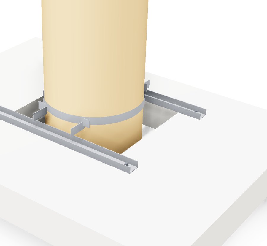
| Supporting frames | Galvanised iron at every slab opening: a 50 × 6 mm flat round frame clamping the chute, arc welded to 50 × 50 × 4 mm angles on 75 × 40 × 4 mm channels bolted to the slab. |
| Control panel | Master panel in the ground floor waste room, with the switches, relays and indication for the door interlock, the cleaning cycle and the exhaust fan. |
By the main contractor and not in our scope: the water supply pipe from the roof tank to the chute head and its connection, and the feed from the fire fighting riser to each sprinkler socket.
In detail
The parts that decide whether it works
At the bottom
What receives the waste
The shaft is the same in every building. What sits under it is the decision that sets how often a truck comes, and it is made from the waste volume and the room, not from a catalogue.
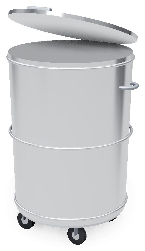
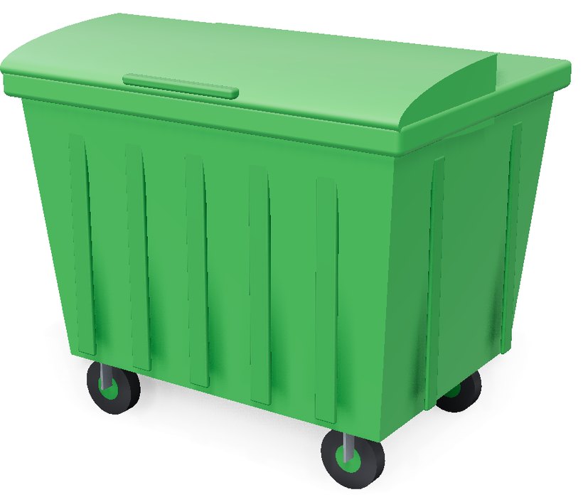
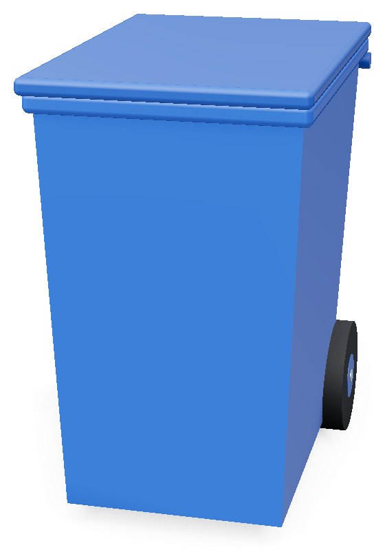
The standard arrangement, and the alternatives
The submittal is issued with a 1.1 m³ steel container to DIN 30700 in the ground floor waste room, which is the arrangement most buildings start from.
Where the volume justifies it, the same shaft discharges into a hydraulic compactor, which reduces the volume roughly four to one before the container, or into a sorter that separates two or three streams at the base. Both are covered on the sorting and compaction page.
Downloads
Technical specifications and material submittals
These are the submittals we issue to consultants and main contractors, with the manufacturer's drawings reproduced in the appendix. Take them into your own submittal, or send them to the consultant as they are.
Issued by CENTRA as the authorised distributor for Ostermeier FZE in Saudi Arabia. Project-specific shop drawings and a door schedule are prepared against your floor plans on request.
Questions
What buyers actually ask
What diameter shaft does a residential tower need?
It follows the number of apartments served per floor, the number of floors and the expected waste volume, not the building's height alone. A standard residential tower is commonly in the 500–600 mm range, but the sizing comes from the project. Send the floor plans and we will size it and mark the shaft on the layouts.
What fire rating do the intake doors have to carry?
That comes from the project's fire strategy and the authority having jurisdiction, not from the chute. Fire rated doors are available, and we state the tested rating for the exact door and wall arrangement being supplied, with the manufacturer's test certificate for the submittal. Ask your fire consultant for the required rating before the shaft is detailed — changing the door schedule afterwards is expensive.
How is odour controlled inside the shaft?
Four things together: an exhaust fan at the top holding the shaft under negative pressure, a cleaning unit washing the interior with water and disinfectant on a cycle, interlocking that limits how long any door stays open, and correct sealing at the floor penetrations. A shaft with only one or two of those will smell, and it is almost always a specification problem rather than a cleaning problem.
Can the doors be locked by floor or by time of day?
Yes. Electrical locking can be applied per floor or on a schedule, from the control panel. Common uses are closing the chute overnight in a residential building, and isolating a floor under renovation so construction debris does not go down a domestic shaft.
What does the ground-floor waste room have to accommodate?
The discharge equipment, the bins, and room to move a full bin out without moving an empty one first. A compactor or sorter needs power, clearance for maintenance access, and drainage. The room is almost always designed too small, because it is sized against the bins rather than against the operation. We mark it on the layout at design stage.
Can a chute be added to a building that already exists?
Sometimes, and the deciding question is whether a continuous vertical route exists — a redundant shaft, a service riser with space, or an external position where a shaft can be built and penetrated at each floor. It is a structural and fire question before it is a chute question, so the answer comes from a site visit rather than from a product catalogue.
Send us your drawings and fire strategy
We will size the shaft, issue a door schedule and lay out the waste room.